OAP Mirrors


  The table below represents a small sample of SORL's broad range of capabilities in producing OAPs. SORL can meet both these standard specifications as well as specialized specifications. Should your component require custom specialized specifications (see How to Specify a Custom OAP), SORL's technical team is always available to provide assistance. Click on custom off Axis Parabolic Worksheet to request information.


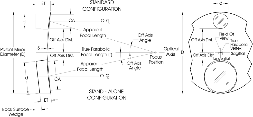
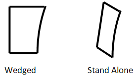
When specifying an OAP, consider the following items:

1. Substrate Material: Zero thermal-expansion ceramic (Zerodur or its equivalent) is the most stable and is our standard. Alternatives include Fused Silica, ULE glasses, conventional metals, and light weighted substrates.

2. Focal Length (FL): True Parabolic or Vertex Focal Length, and off-axis Apparent Focal Length (AFL), should be considered. Only the focal length, measured along optical axis from vertex to focus position, need be specified.

3. Off-Axis Distance (OAD): Specified along a perpendicular from optical axis to inner edge of mirror.

4. Outer Diameter (OD): Outer mirror diameter measurement compatible with physical requirements.

5. Clear Aperture (CA): The optically qualified region of the mirror surface.

6. Edge Thickness (ET): To insure structural stability, a mirror will typically be made from a blank having a 6:1 diameter-to-thickness ratio. For stand-alone mirrors, this is approximately correct. Standard OAPs sectioned from a larger diameter parent will be thicker.

7. Surface Accuracy- Deviation from perfect paraboloidal shape, specified as "peak-to-peak" (peak-to-valley) value in fractions of the interferometric test wavelength 0.6328 microns. Due to reflection at the surface, the wavefront error is twice the surface error.

8. Surface Quality or Finish: A measure of the optical polish, specified by "scratch/dig" values denoting surface imperfections, as defined by Military Specifications, MIL-0-1383. Typical Scratch/Dig specifications:

80/50 Standard IR quality 
60/40 Visible to IR 
40/20 UV to Visible Laser 
20/10 UV and High Power Laser 

9. Optical Coatings: May be selected from a variety of evaporated metals and dielectric materials for optimal performance in the wavelength region, optical power level, and environment of intended operation.

AlSiO, our standard, is the most durable coating and has high reflectivity from Visible through the IR. 
Enhanced Silver is better for higher power and has higher average reflectivity from Visible through the IR. 
Gold 
AlMgF2

Clocking Orientation

SORL Mounts identify the clocking orientation of your OAP, which specifies the OAP focus position and dictates location of the Reference Flat. Using the mirror at this correct rotational position will assure optimum wavefront performance. This is the position at which the mirror was fabricated and tested. (See Mirror/Mount Assembly)

NOTE: Please include the clocking orientation on your order. Other orientations are possible, but may impact your final cost. Your SORL representative is always available to assist you with any clocking orientation questions you may have. 

Request A Quote for A Custom OAP


Model  Number

Vertex Focal
Length (in)

Off Axis Distance
to Edge (in)

Diameter
(in)


03-015-01

3

1.5

1

Please Note:  
All of these Catalog Mirrors
are manufactured as Parent
Cut-outs and are in the “wedged”
configuration in which the edge
thickness will not be uniform
and the rear surface will be
perpendicular to the optical axis

However, Model Numbers with *
denotes that these are
manufactured in the
“Stand Alone” configuration in
which the edge thickness will be
uniform and the rear surface not
perpendicular to the optical axis. 


03-005-02

3

0.5

2

04-025-01

4

2.5

1

04-015-02

4

1.5

2

04-005-03

4

0.5

3

06-04-01

6

4

1

06-03-02

6

3

2

06-02-03

6

2

3

06-01-04

6

1

4

12-047-01

12

4.7

1

12-037-02

12

3.7

2

12-027-03

12

2.7

3

12-17-04

12

1.7

4


12-007-05

12

0.7

5


18-07-02

12

7

2


18-06-03

18

6

3


18-05-04

18

5

4


18-03-06

18

3

6


18-01-08

18

1

8


20-03-02

20

3

2


20-02-03

20

2

3


20-01-04

20

1

4


25-025-02

25

2.5

2


25-075-02

25

7.5

2


25-055-04

25

5.5

4


25-035-06

25

3.5

6


25-015-08

25

1.5

8


30-025-02

30

2.5

2


30-075-02

30

7.5

2


30-055-04

30

5.5

4


30-035-06

30

3.5

6


30-015-08

30

1.5

8


30-04-08*

30

4

8


30-02-10*

30

2

10


40-025-02

40

2.5

2


40-075-02

40

7.5

2


40-055-04

40

5.5

4


40-035-06

40

3.5

6


40-08-06*

40

8

6


40-015-08

40

1.5

8


40-06-08*

40

6

8


40-04-10*

40

4

10


40-02-12*

40

2

12


60-10-04

60

10

4


60-08-04

60

8

4


60-04-06

60

4

6


60-06-06

60

6

6


60-08-06

60

8

6


60-04-08

60

4

8


60-06-08

60

6

8


60-04-10

60

4

10


60-02-10

60

2

10


60-02-12

60

2

12


60-02-16*

60

2

16


80-08-04

80

8

4


80-06-06

80

6

6


80-04-06

80

4

6


80-08-06

80

8

6


80-04-08

80

4

8


80-06-08

80

6

8


80-02-10

80

2

10


80-02-16*

80

2

16


100-06-06*

100

6

6


100-08-06*

100

8

6


100-06-08*

100

6

8


100-04-08*

100

4

8


100-02-08*

100

2

8


100-02-10*

100

2

10


100-04-10*

100

4

10


100-02-12*

100

2

12


100-02-14*

100

2

14


100-16-16*

100

16

16


100-02-16*

100

02

16


100-04-24*

100

4

24


Request a Quote for a Catalog OAP


Using the Chart as a Guide When Ordering Precision Mirrors and Mounts:

Ordering Information Example:

Order Number: OAP40-015-08

40 = 40 inch parabolic or vertex focal length 
015 = 1.5 inch off-axis distance - specified along perpendicular from optical axis to inner edge of mirror 
08 = 8 inch diameter 

Standard Manufacturing Tolerances

Focal length: +/- 0.5% 
Diameter: +.000" -.005" 
Off-Axis Distance: +/-0.02" (standard configuration), +/- 0.125" (stand-alone configuration) 
Edge Thickness: +/-0.05" (12" focal length or less), +/-0.10" (18" focal length or greater) 
Surface Quality: 60/40 
Surface Accuracy: Specified over 90% of the clear aperture area (Test Wavelength 0.6328 microns) 

Notes

1. Standard Coating: AlSiO. 
2. Focus Position of the OAP is oriented in the mount at 9 o'clock unless otherwise specified. 
3. Stand-alone configuration OAPs are manufactured directly as off-axis segments. 
4. High Quality (Q) Mirrors are l/8  from 12" focal length and longer. l/5 from 3" to 6" focal length. 
5. Superior Quality (SQ) Mirrors are up to l/20 (please specify when requesting a quote).